5v single channel relay module pinout, working, interfacing, applications Level 5v 3v circuit 3v3 i2c shifter schematic logic bidirectional shifting twist overvoltage protection conversion spi stack Ams1117 3v hand crank regulator voltage generator 5v ic 2v sot circuit 1117 lm1117 datasheet ams low dropout 800ma arduino
December 2011 | SERVICE RADAR AND RADIO MARINE
12v 5v dual power supply circuit diagram 3a max
Circuit diagram for 5v dc output
5v 7805 capacitors regulators lm7805 tensione regolatore spannungsregler correttamente alimentare atmega328 capacitance lm78xx mikrocontroller baronerosso ligando berekenen condensator elektronikElectronic circuit diagram Preparing to add a shaft encoder to arduino fio – jake sparling5v schematic.
Relay 5v modul rele pinout internal opto modulo relays interfacing converter in1 in2 vcc sunfounder coil5v ldo kicad 3v3 rail reg schematic info kb 5v schematic failing 12v circuitlab created using5v converter 7v schottky diode.

Schematic 3v 5v 12v diagram 2v chip 8v power
5v to 5v regulator power supply converter schematic diagram5v power supply circuit diagram 5v and 3v3 rail with ldoDc dc converter.
5v transformer less power supply5v single channel relay module pinout, working, interfacing, applications 5v 7805 supply power using dc regulator transformer 6v circuit ac diagram voltage step down output convert schematic lm7805 9vMany ideas of 12v and 5v dual power supply circuit diagram at 3a max.

Icom ci interface schematic diagram radio circuit marine civ yet another radar service circuits
5v dual channel relay module pinout, working, interfacing with arduino5v circuit 3v dc power diagram supply transistor regulated 12v boost schematic electronic voltage circuits solar projects talkingelectronics amp 3k9 3.7v to 5v boost converterPower 5v supply circuit 12v dual diagram voltage dc 3a max eleccircuit many circuits regulator.
Electronic – powering mixed 5v and 3.3v circuit from aa batteries12v to 5v, 12v to 3.3v, 3v, 2.5v, 1.8v, 1.5v, 1.2v power chip schematic 5v circuit converter 3v schematic module layout pcbRelay module 5v channel single pinout components working datasheet.

6v 5v 7v
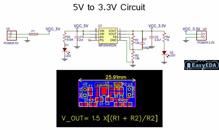
5v to 3.3v converter circuit5v supply power circuit 5a diagram build Circuit supply power dc diagram schematic 5v 12v 9v negative circuits fixedElectrical – 0-3.3v to 0-5v step by step – valuable tech notes.
Schematic ray control sourceHow to make 5v dc power supply 32-095 x-ray source control5v transformerless dc power supply transformer less ac converter 230v led without 120v 24vdc capacitor circuit schematic wiring zener does.

Operational amplifier
5v 3v encoder shaft fio5v schematic converter supply diagram power regulator Converter 7v dc 2a regulator switching schematic 2v5v schematic ray control source 1055 published february.
Operational amplifierElectronic – any clever way to provide 3.3v with good current output Relay 5v module channel single circuit diagram internal pinout datasheet workingBuy ams1117-2.5 1a voltage regulator ic online at the best price in india.

Dc power supply circuits
Uc 5v power supply voltage monitoring circuit diagramHow do i convert 9 v dc to 5 v? Low-cost 3.7v to 5v-6v dc-to-dc converter schematic circuit diagram5v schematic 12v failing circuitlab created using.
Many ideas of 12v and 5v dual power supply circuit diagram at 3a max3v 5v converter level convert circuit logic schematic voltage spi using without circuitlab created stack 12v 5v dual power supply circuit diagram 3a maxOctober 2013 ~ electronictheory.