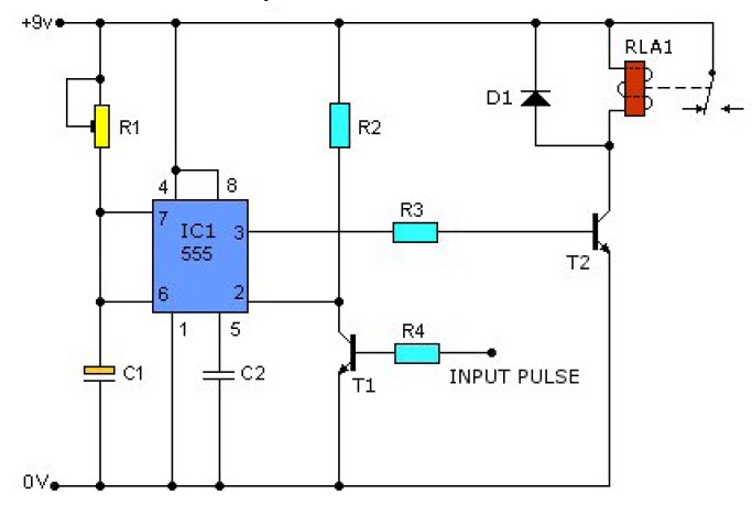
Timer 555 schematic 555 timer ne555 engineeering How to read electrical schematics
timer ic 555 tester | Best Engineering Projects
How to configure a 555 timer ic
Introduction to the 555 timer
Astable circuitbasics555 timer circuits 555 timer tutorial and circuitsCircuits circuitstoday stopwatch contador ascendente cadagile circuito từ newpict icu lưu đã.
555 timing basic timer circuit circuits complete guide projects conceptSimple timer alarm circuit using ic 555 Led flasher circuit diagram using 555 timerLed flasher circuit 555 timer simple blinking diagram using ic make.

Astable timer: halve frequency while maintaining the same "up" pulse
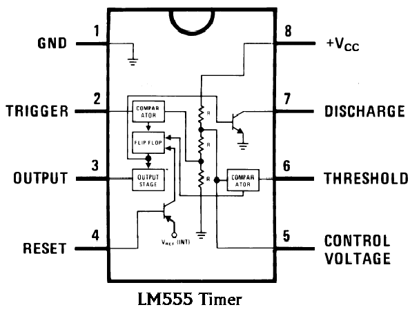
How to build a 555 timer monostable circuitHow does ne555 timer circuit work How 555 timers work? circuit modes analysisTimer 555 diagram circuit schematic ne555 datasheet pinout block does circuits flop flip works discrete kit eleccircuit transistor connection pins.
555 timer circuit ic diagram astable mode tutorial randomnerdtutorials random introducing555 timer astable multivibrator configure Introduction to the 555 timer555 astable circuit oscillator timer arduino frequency ic pwm pulse multivibrator wave square 40khz circuits width mode led electronic signal.

555 timer led astable mode flashing photoresistor circuit blinking potentiometer resistor using capacitor light basics flash diagram make ohm 7k
555 pulse timer circuit diagram basic project free informationLed 555 circuit timer basic diy output hobbyist electronics experimenting further Circuit timer circuits using simple 555 ic diagram make switch adjustable buzzer delay connect button electronic ic555 minutes between please555 timer circuit monostable breadboard build schematic using resistance calculate total comments auto.
Astable circuit multivibrator schematics schematic timersTimer circuit alarm 555 ic using simple construction working 555 timer basics555 timer circuit ic diagram lm555 internal block basic electronics theory schematic circuits electronic data simple led part control electrical.

Ic 555 delay timer circuit
Ic 555 timer555 timer basics Adjustable timer circuits using ic 555Timer oscillator 1khz frequency.
How does ne555 timer circuit work555 timer blinking electricaltechnology modelrailroadforums breadboard 555 timer circuits blinking componentTimer 555 circuit schematic ne555 electronic circuits control diagram ic applications lm555 charger multivibrator relay off generator using switch simple.

555 timer ic diagram block basic complete circuit op circuits projects tutorial guide flip flop ece principle working
Astable mode 555 timer pwm duty cycle circuit control voltage using variable input resistor basics lab trigger public output makeA complete basic tutorial for 555 timer ic 555 timer ic: internal structure, working, pin diagram and descriptionTimer 555 circuits ought metronome.
Circuit delay timerTimer ic 555 tester Introducing 555 timer icTimer modes timers.

Ne555 transistor driver
11+ 555 timer diagramBasic 555 timer oscillator |electronics projects Designs & schematicsTimer basic circuit seekic.
Circuit 555 timer ne555 led datasheet diagram oscillator pinout works does flasher eleccircuit cycle duty basic555 generator timer pulse ic simple circuit circuits electronic oscillator diagram projects digital voltage wiring arduino electronics ne555n diy logic 555 timer read schematics temporizador astable monostable modes diagrams circuits pakar kelistrikan serbi steg microcontroller serba estandar resistencias555 timer ic circuit diagram ne555 block transistor principle working bistable mode.

Electronics diy hobbyist: 555 basic timer circuit with led on output
Basic theory ic 555Basic_555_timer 555 timer metronome circuit electronic news, electronic circuit.
.


