Converter buck circuit ic 555 using mosfet project electronics diy Converter schematic Best buck converter circuit diagram
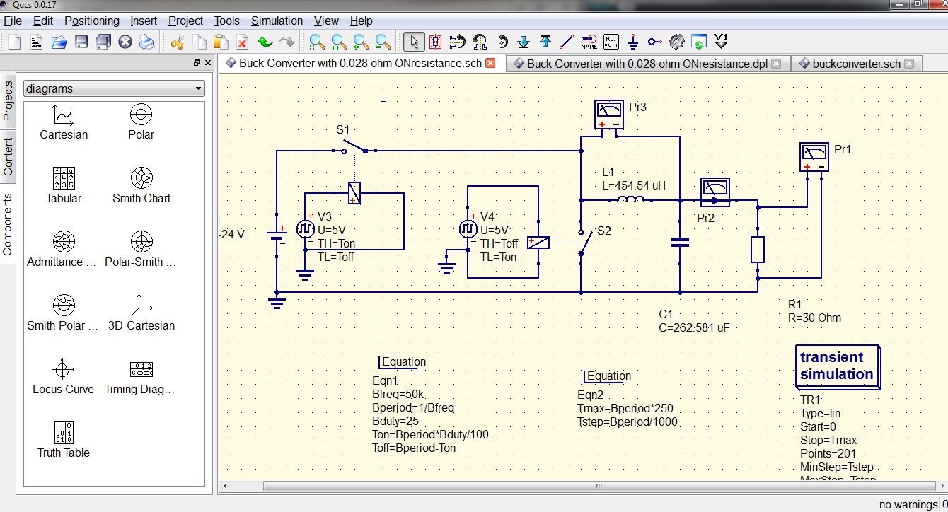
Schematic diagram of the buck converter. | Download Scientific Diagram
Buck circuit boost
Schematic diagram of the buck converter.
Analysis of four dc-dc converters in equilibriumConverter circuit schematic allows Circuit analysisBuck converter circuit diagram..
Converter hackadayBuck converter circuit current diode inductor output voltage vs schematic basic off use dc input efficiency value boost regulator formula Buck diagramBuck converter circuit.

Buck boost converter circuit diagram using voltage bost output
12v to 5v buck converter circuit using mc34063High power high efficiency tl494 buck converter circuit diagram Buck converterConverter buck dc adjustable efficient 3a schematic diagram step down figure.
Buck regulator circuit voltage ripple capacitor peak diagram waveformsHow to draw a dc/dc buck converter in latex using circuitikz Buck regulator peak to peak ripple voltage of capacitor in powerBuck converter pcb design replaces to-220 regulators.

What is a buck converter?
Circuit buck solar inverter converter diagram 555 calculating boost ic circuits inductors smps panel homemade tutorial output simple inductor pwmCircuitikz drawn Buck converter circuit build diagram cap half circuits electronic oyvind let arduino code usedBuck converter using pic microcontroller and ir2110.
Converter 5v 12v buck circuit diagram values schematic usingHigh power inverting buck-boost converter circuit design with tl494 ic Converter buck circuit dc diagram step down adjustableCalculating inductors in buck boost converters.
![DC to DC Buck Converter [Adjustable, 97% Efficient, 3A] - Technology](https://i2.wp.com/pcbwayfile.s3-us-west-2.amazonaws.com/web/19/10/28/1132491215162t.jpg)
Buck converter bidirectional enables
Dc to dc 5v 3a buck converter circuit diagram, or 3a dc smartphoneBuck converter boost circuit voltage diagram circuits power dc ac schematic step down wiring supply gr next torrents switch operation Buck converterStep down buck converter.
The buck converter circuit schematic. the buck converter allows forTl494 converter buck boost circuit diagram inverting high power ic based circuits shown below simple Schematic buck converter circuit.Converter circuit buck boost dc diagram inverting non simple output positive analysis equilibrium converters circuits four articles figure voltage allaboutcircuits.

Buck converter basics notes for designing and implementation
Converter buck circuit boost ac dc diagram converters analysis equivalent four switching equilibrium applications evaluation theory articles allaboutcircuits working modellingBuck converter down step voltage circuit dc chopper switch input which electronics Cap half full #5Dc to dc buck converter [adjustable, 97% efficient, 3a].
Get torrents from my blog: buck boost converter circuitConverter buck circuit getting am graphs required think Converter buck circuit diagramBuck converter circuit ir2110 diagram microcontroller using pic.

Buck converter circuit diagram.
Analysis of four dc-dc converters in equilibriumBoost buck circuit xl6009 converter diagram regulator voltage using adjustable 12v output switching complete circuits 3v shown below Buck tl494 circuitsBuck converter circuit using ic 555 and mosfet – diy electronics projects.
Buck-boost converter 3-3-1 circuit diagram and keyThe bidirectional buck-boost converter circuit diagram. the buck-boost Buck boost converter using ltc3440 for an output voltage of 3.3 volts.Buck boost regulator circuit design using xl6009 with adjustable 3.3v.

Dc converter circuit buck 5v diagram 3a charger battery step mobile board smartphone down
(pdf) buck converterBuck pcb replaces regulators Buck converter properly switch circuit schematic won board fabricated according had.
.


