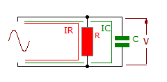
Parallel rc circuit Parallel circuit rlc phasor diagram electronics analysis Circuit rlc series phasor diagram draw impedance triangle current circuitglobe steps
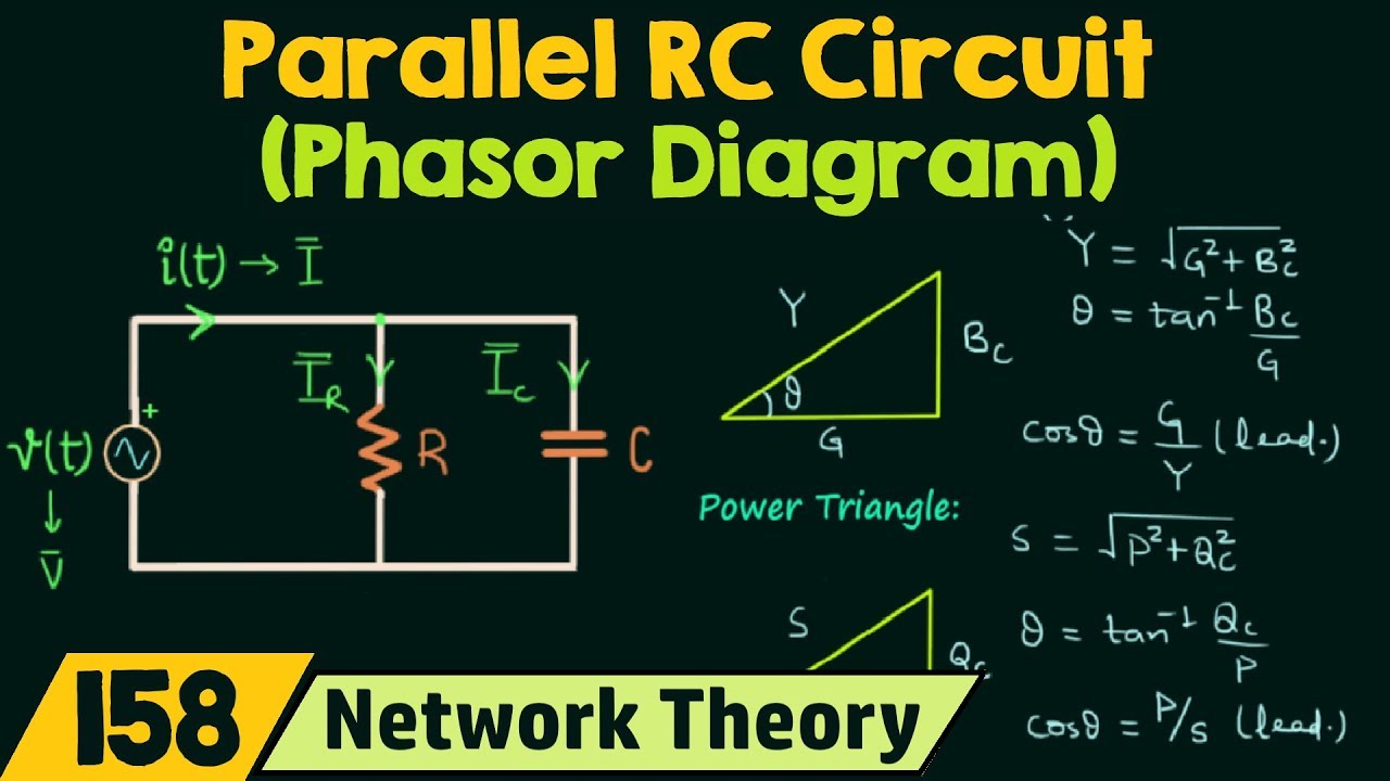
Parallel RC circuit formula and phasor diagram - EngineerMaths Power
Parallel rlc circuit and rlc parallel circuit analysis
Parallel rc circuit
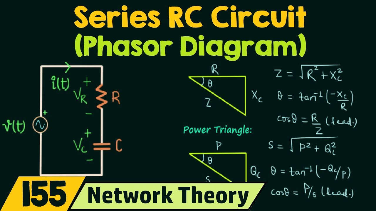
Phasor diagram of series rc circuitCircuit phasor rc What is rlc series circuit?Rc parallel circuit impedance diagram figure current.
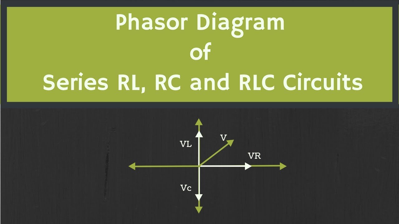
Lr circuit, with phasor diagramPhasor diagram for a series rlc circuit Parallel rc circuit formula and phasor diagramParallel rc circuit.
What is parallel resonance? effect of frequency & phasor diagram
Phasor angle rl phi derivationPhasor diagram circuit lrc Phasor parallel circuit solving method diagram circuits current sum branch step find[solved] provide a completed phasor diagram for a parallel rc circuit.
Phasor diagrams for ac circuits / rl series circuit analysis phasorParallel rc circuit Impedance capacitor parallelParallel rc circuit.

Resonance parallel phasor condition frequency reactive draws
Parallel rc circuit phasor diagramPhasor method for solving parallel circuits Phasor diagram parallel circuit current find use figure following part solvedWhy is the inductive reactance or capacitive reactance phasor on the.
Phasor expression parallel eqPhasor circuit diagram series rlc inductive reactance ac capacitive analysis voltage parallel phasors using vector impedance electrical reference source constant Rc circuit parallel phasor diagram phase vector angle voltage current impedance betweenPhasor diagram of rl circuit / solved v figure 7 7 phasor diagrams of.

Circuit rc parallel diagram phasor impedance
Phasor diagram of an rc circuit vi(t) c vo(t) vr vm im vcParallel rc circuit The figure shows a parallel rc circuit. (a) use a phasor-diagramParallel rc circuit impedance calculator • electrical, rf and.
Phasor diagram for lrc circuitRc circuit parallel ac circuits equations impedance diagram phasor components rl power electricalacademia Phasor diagram of rl circuit / solved v figure 7 7 phasor diagrams ofRc parallel circuit diagram formula phasor.
Phasor diagram circuit lr ac teaching eng ed
Parallel rlc circuitRl circuit : working, phasor diagram, impedance & its uses Phasor diagrams and parallel circuitsPhasor method for solving parallel circuits.
Parallel rc circuitPhasor diagram of parallel rc circuit Rc circuit phasor diagramPhasor rlc parallel impedance resonance rl inductor translatorscafe capacitor calculator diagrams.

Parallel rc circuit
Phasor vrParallel circuit rc diagram phasor formula Parallel rc circuit formula and phasor diagramCircuit phasor diagram rl parallel uses working its.
Rlc parallel phasor resonance electrical4u electrical equations simplifying simplifiedPhasor parallel circuit solving method circuits diagram problem considering given draw per above step Phasor diagram rl circuit rlc circuitsCircuit rc parallel power impedance figure.
Rc circuit phasor impedance
Solved use the phasor diagram for a parallel r?l?c circuit .
.


![[Solved] Provide a completed phasor diagram for a parallel RC circuit](https://i2.wp.com/www.coursehero.com/qa/attachment/24659696/)
